RO/NF is the separation of one component of a solution from another component by means of pressures exerted on a semipermeable membrane. Removal of ionic, organic and suspended / dissolved impurities occurs during the RO/NF process. Unlike a filter, which separates by "normal" filtration, the membrane separlator separates using a process called crossflow filtration. Feedwater solution is separated into two streams, permeate and concentrate, and collected from both sides of the membrane. A semipermeable RO/NF membrane, under sufficient pressure, allows passage of purified water while rejecting and concentrating dissolved and suspended solids.
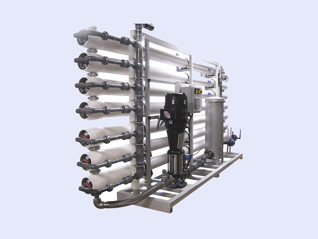
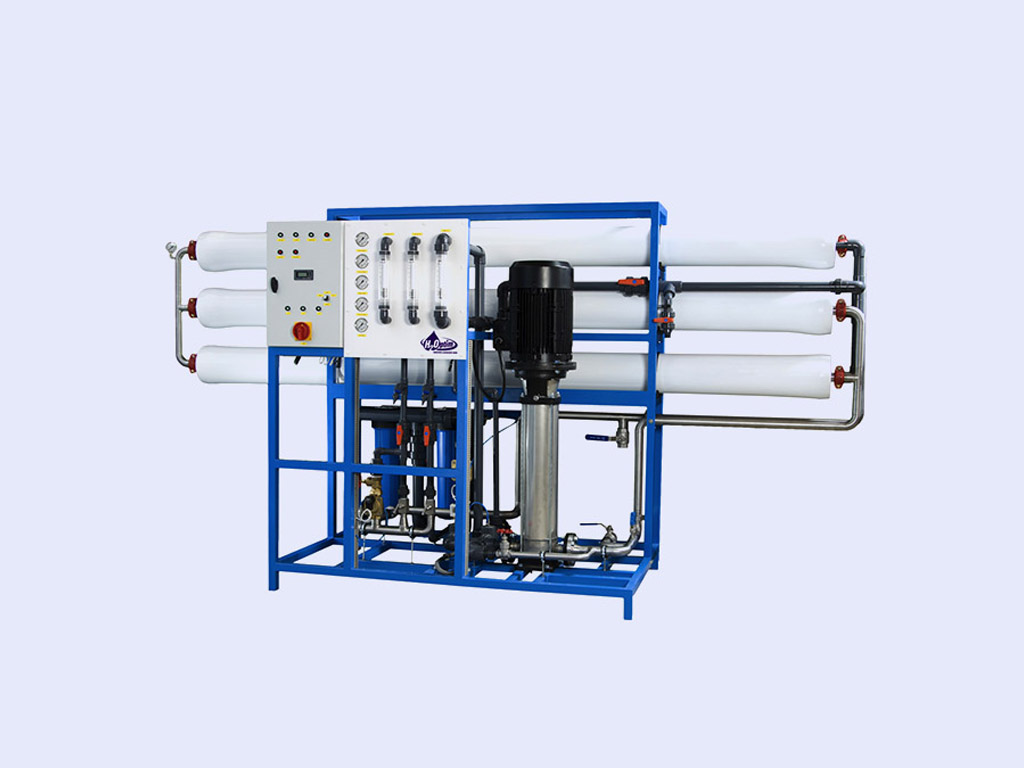
The system use spiral-wound membrane package, with a turbulent flow design. This membrane module, called a separlator, collects the purified water within a central tube, the permeate tube.
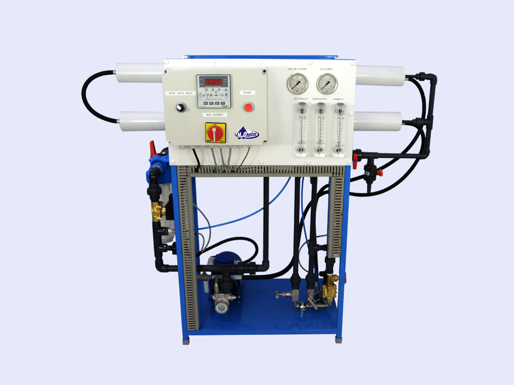
The feedwater passes through a replaceable 5-micron cartridge filter, which removes bulk suspended solids. Filtered water then flows to the inlet solenoid valve, which opens when the machine is turned on, allowing water to flow to the pump inlet. When the machine is turned off, the valve closes, preventing non-turbulent flow through the separlators, which would lead to shortened membrane life.
The pump feeds water to the separlator housings arranged in parallel combinations. The direction of water flow is indicated by an arrow on each separlator housing. Water is separated by the membrane within the separlators and leaves the separlator housings in two streams: permeate and concentrate.
Permeate from each separlator housing is collected in a common manifold. The permeate then flows through a flow meter and to the permeate outlet point of the machine. Permeate should be collected in no pressure storage tank. It could be directed with some backpressure but it must be never higher than Final Pressure of concentrate. It must be considered that backpressure decrees flow rate and water quality. The permeate quality depend on inlet water and is generally described as a MgSO4 removal up to 96-98%.
The concentrate leaves separlator housings and flows to the flow control center (recycle/concentrate manifold). At this point, the recycle valve channels a predetermined amount of concentrate into the pump inlet Recycle increases recovery while maintaining adequate crossflow through the separlators. The other concentrate valve controls the amount of concentrate flowing to the drain; it controls the pressure within the machine; and it helps control the system recovery. An autoflush solenoid valve is added parallel to concentrate valve with an additional tee. The concentrate then flows to the concentrate outlet point of the machine.
Technical Data (base Line models*):
|
Model |
Permeate Flow Rate |
Membrane size |
Efficiency |
Operating pressure1 |
Power cons.2 |
|
|
ULP** |
BW** |
|||||
|
Osmo Optim 2k |
0,1 |
2,5” |
50 |
8-16 |
0,35 |
|
|
Osmo Optim 7k |
0,3 |
2,5" |
75 |
8-16 |
0,55 |
|
|
Osmo Optim 12k |
0,5 |
4" |
75 |
8-16 |
1,10 |
|
|
Osmo Optim 21k |
0,8 |
4" |
75 |
8-21 |
1,4 |
2,5 |
|
Osmo Optim 24k |
1,0 |
4" |
75 |
8-21 |
1,6 |
2,7 |
|
Osmo Optim 43k |
1,6 |
4" |
75 |
8-21 |
1,9 |
3,2 |
|
Osmo Optim 48k |
2,2 |
8" |
75 |
8-21 |
2,0 |
3,4 |
|
Osmo Optim 72k |
3,0 |
8" |
75 |
8-21 |
3,3 |
5,5 |
|
Osmo Optim 96k |
4,0 |
8" |
75 |
8-21 |
4,5 |
7,0 |
|
Osmo Optim 144k |
6,0 |
8" |
75 |
8-21 |
6,0 |
10,0 |
|
Osmo Optim 192k |
8,0 |
8" |
75 |
8-21 |
7,0 |
11,0 |
|
Osmo Optim 240k |
10,0 |
8" |
75 |
8-21 |
9,0 |
15,0 |
* Other models for individula design for request
** LE – Low Energy Membranes, HP – High Pressure Membranes
1 Operating pressure depend on membrane type and water temperature
2 Calculated power. Final Power May be diffrent depend on pump model and parameters assumed for final design